


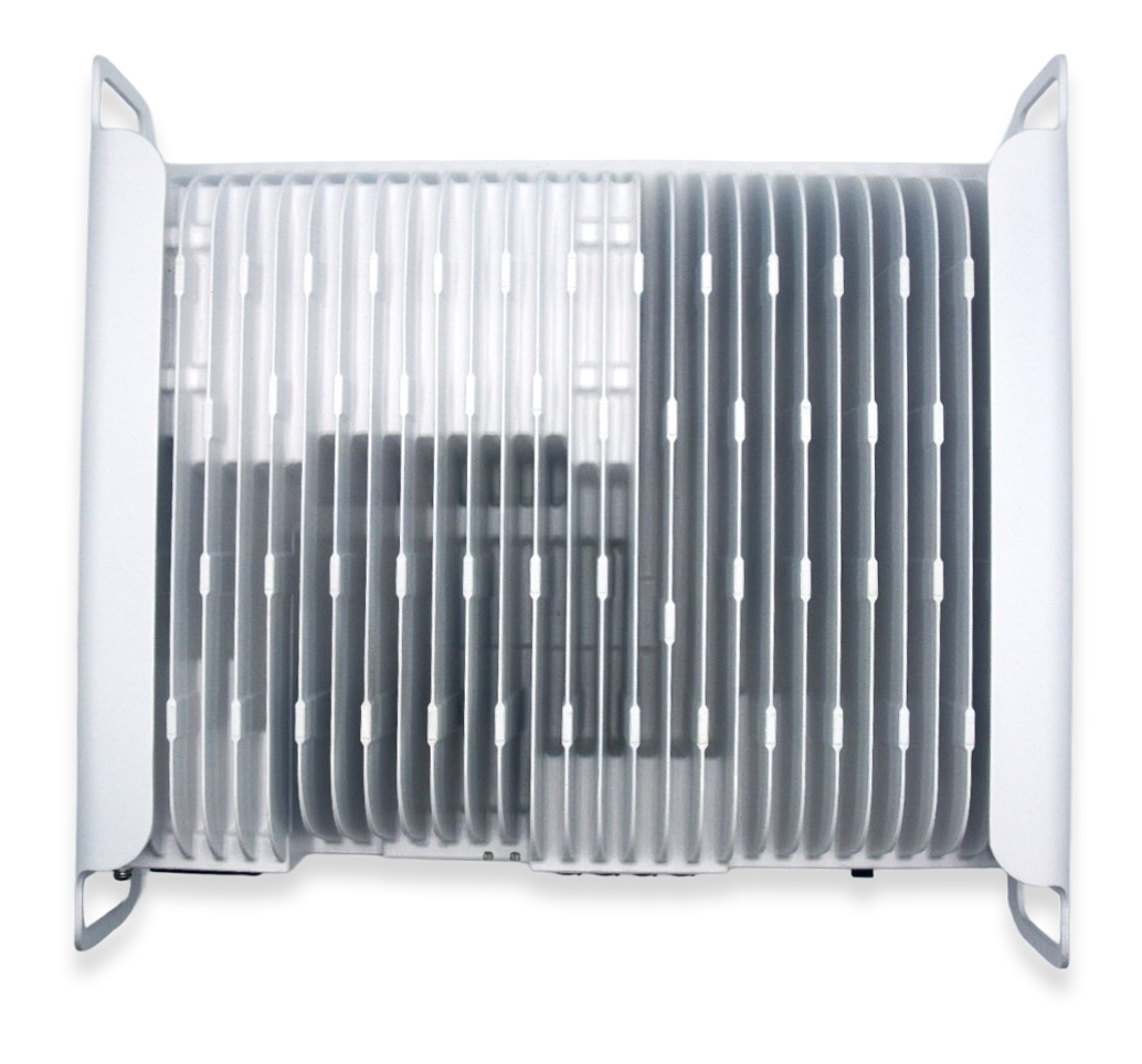


BARS Components & Specifications
The SOLiD BARS DAS system is comprised of three main active components.
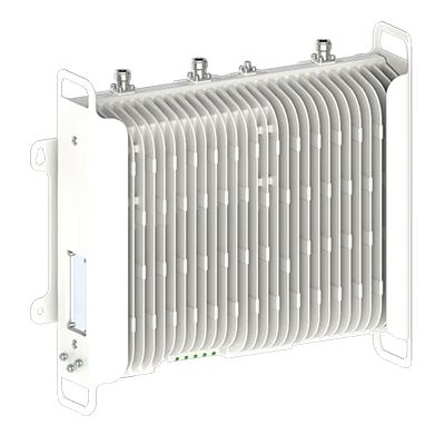
BARS System Core
Receives and digitizes signals from up to three mobile operators, then delivers data and power to Remote Units via dedicated Ethernet cables.
| Category | Parameter | Specification | Remarks |
|---|---|---|---|
| Physical | Dimensions (W × D × H) | 352 × 267 × 88 mm (2U) | Without mounting bracket |
| Volume | 8.3 L | ||
| Weight | ≤ 7.9 kg | Excl. wall-mount bracket; tolerance ±0.2 kg | |
| Color / Finish | Jevisco PP#4636 X-Texture, semi-gloss white powder coating | ||
| Power | Power input | AC 90–264 V, 47–63 Hz | |
| Power consumption | < 500 W | With 8 RUs connected via 100 m PoE cables | |
| Connectivity & cabling | Optical fiber distance | Up to 10 km | HE–HUB |
| Ethernet cable distance (CAT6A) | Up to 100 m | HE–RU | |
| Ethernet cable distance (CAT6A) | Up to 200 m | HE–Extender–RU | |
| Ports — top | RF port | N-type (female), 3 ports | Donor antenna |
| Wi-Fi antenna port | Reverse SMA-type (female), 1 port | Installer-accessible | |
| SIM card slot | 1 slot | For EMS modem | |
| Ports — bottom | RU interface | RJ45 with PoE, 8 ports | |
| LAN interface | RJ45, 1 port | ||
| Console / local interface | USB Type-C, 1 port | ||
| HUB interface | SFP+, 4 ports | ||
| Power input | AC power port, 1 port | ||
| Ground | GND terminal, 1 | ||
| Indicators | Status LEDs | 5 LEDs (bi-color: Green / Red) | |
| Installation | Mounting options | Wall mount (vertical only); rack mount (horizontal only) | |
| Environmental | Ingress protection | IP40 | |
| Cooling | Natural convection | Fanless | |
| Operating temperature | –5 °C to +40 °C | Rack or wall mount | |
| Storage temperature | –40 °C to +70 °C |

BARS System Core
Receives and digitizes signals from up to three mobile operators, then delivers data and power to Remote Units via dedicated Ethernet cables.
| Category | Parameter | Specification | Remarks |
|---|---|---|---|
| Physical | Dimensions (W × D × H) | 352 × 267 × 88 mm (2U) | Without mounting bracket |
| Volume | 8.3 L | ||
| Weight | ≤ 7.2 kg | Excl. wall-mount bracket; tolerance ±0.2 kg | |
| Color / Finish | Jevisco PP#4636 X-Texture, semi-gloss white powder coating | ||
| Power | Power input | AC 90–264 V, 47–63 Hz | With 8 RUs connected via 100 m PoE cables |
| Power consumption | < 500 W | ||
| Connectivity & cabling | Optical fiber distance | Up to 10 km | HE–HUB |
| Ethernet cable distance (CAT6A) | Up to 100 m | HUB–RU | |
| Ethernet cable distance (CAT6A) | Up to 200 m | HUB–Extender–RU | |
| Ports — bottom | RU interface | RJ45 with PoE, 8 ports | |
| Console / local interface | USB Type-C, 1 port | ||
| HE interface | SFP+, 1 port | ||
| Power input | AC power port, 1 port | ||
| Ground | GND terminal, 1 | ||
| Indicators | Status LEDs | 2 LEDs (bi-color: Green / Red) | |
| Installation | Mounting options | Wall mount (vertical only); rack mount (horizontal only) | |
| Environmental | Ingress protection | IP40 | |
| Cooling | Natural convection | Fanless | |
| Operating temperature | –5 °C to +40 °C | Rack or wall mount | |
| Storage temperature | –40 °C to +70 °C |
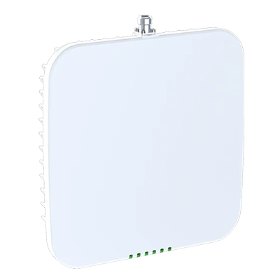
BARS System Core
Receives and digitizes signals from up to three mobile operators, then delivers data and power to Remote Units via dedicated Ethernet cables.
| Category | Parameter | Specification | Remarks |
|---|---|---|---|
| Physical | Dimensions (W × D × H) | 250 × 250 × 44 mm | Without mounting bracket |
| Volume | 2.75 L | ||
| Weight | ≤ 2.4 kg | Excl. wall-mount bracket; tolerance ±0.2 kg | |
| Color / Finish | Semi-gloss white powder coating (Jevisco PP#4636 X-Texture) | ||
| Power | Power input | –57 VDC to –41.1 VDC | PoE supplied from HE or HUB |
| Power consumption | < 40 W | ||
| Connectivity & cabling | Ethernet cable distance (CAT6A) | Up to 100 m | HE–RU or HUB–RU |
| Ethernet cable distance (CAT6A) | Up to 200 m | HE–Extender–RU or HUB–Extender–RU | |
| Ports | RF port | N-type (female), 1 port | DAS antenna |
| Ethernet / power | RJ45 with PoE, 1 port | ||
| Indicators | Status LEDs | 6 LEDs (bi-color: Green / Red) | |
| Installation | Mounting options | Wall mount; ceiling mount | |
| Environmental | Ingress protection | IP40 | |
| Cooling | Natural convection (fanless) | ||
| Operating temperature | –5 °C to +45 °C | Wall mount | |
| Operating temperature | –5 °C to +40 °C | Ceiling mount | |
| Environmental | Storage temperature | –40 °C to +70 °C |
Channel and band configuration
| Band | DL freq. (MHz) | UL freq. (MHz) | Full BW (MHz) | Max. channel BW (MHz) | Carrier support |
|---|---|---|---|---|---|
| Band 4 (AWS-1) | 2110–2155 | 1710–1755 | 45 | 20 | Verizon / AT&T / T-Mobile |
| Band 5 (Cellular) | 869–894 | 824–849 | 25 | 10 | Verizon / AT&T / T-Mobile |
| Band 12 (700 Lower) | 729–746 | 699–716 | 17 | 10 | AT&T / T-Mobile |
| Band 13 (700 Upper) | 746–756 | 777–787 | 10 | 10 | Verizon |
| Band 25 (PCS) | 1930–1995 | 1850–1915 | 65 | 20 | Verizon / AT&T / T-Mobile |
System RF performance
| Parameter | Direction | Unit | Specification |
|---|---|---|---|
| Total bandwidth | DL / UL | MHz | See band configuration |
| Max. channel bandwidth | DL / UL | MHz | See band configuration |
| Number of MNOs | DL / UL | MNOs | Up to 3 |
| Number of bands per MNO | DL / UL | Bands | Up to 3 |
| Output power | DL | dBm | ≤ 17 dBm EIRP (composite per band), ≤ 10 dBm per channel |
| UL | dBm | 22 ± 2 dBm per band / MNO | |
| Input power (RSRP) | DL | dBm | –120 dBm to –40 dBm |
| System gain | DL / UL | dB | Maximum ≤ 100 dB |
| EVM | DL | % | ≤ 8% (64-QAM) |
| UL | % | ≤ 8% (16-QAM) | |
| Interference cancellation | DL / UL | dB | Maximum 30 |
| Noise figure | DL / UL | dB | Typical 5.0 dB (± 2.0 dB) |
Compliance
| Category | Parameter | Specification |
|---|---|---|
| Regulatory | FCC | Complies with FCC Part 15 and Part 20 |
| UL | Certified to UL 62368-1 | |
| Installation | Intended for fixed, in-building use only | |
| RF exposure | Minimum separation distance: 41 cm (16 in) for donor antennas, 20 cm (8 in) for DAS antennas |
Premium Scalability with SOLiD BARS
One BARS Headend supports up to four Hub Units, each designed to handle up to eight Remote Units. Modular architecture enables a wide range of configuration possibilities to fit any Middleprise facility – from a small office to a corporate campus.
Every SOLiD BARS in-building DAS solution is custom-designed to address varying coverage requirements, building layouts, signal environments, and budgets.
SOLiD BARS Solution Configurations
The Headend Unit receives off-air AT&T, T-Mobile, and Verizon signals via three outdoor directional antennas. Eight Remote Units amplify and distribute reliable multi-carrier coverage up to 100,000 sq ft* using a system of indoor antennas.
* Coverage values are estimated. Actual results vary based on outdoor signal conditions and building layout.

The Headend Unit receives off-air AT&T, T-Mobile, and Verizon signals via three outdoor directional antennas. Two Hub Units extend system reach to higher levels or separate buildings using fiber cabling. A total of 24 Remote Units amplify and distribute reliable multi-carrier coverage up to 300,000 sq ft* using a system of indoor antennas.
* Coverage values are estimated. Actual results vary based on outdoor signal conditions and building layout.

The Headend Unit receives off-air AT&T, T-Mobile, and Verizon signals via three outdoor directional antennas. Four Hub Units extend system reach to higher levels, distant wings, or separate campus buildings using fiber cabling. A total of 40 Remote Units amplify and distribute reliable multi-carrier coverage up to 500,000 sq ft* using a system of indoor antennas.
* Coverage values are estimated. Actual results vary based on outdoor signal conditions and building layout.

Frequently Asked Questions
Who is SOLiD BARS For?
A SOLiD BARS DAS solution is designed for facilities that need reliable cellular coverage throughout without the cost and complexity of an Active DAS. Applications include:
- Commercial Offices
- Hospitals and Healthcare Clinics
- Schools and Universities
- Hotels and Hospitality Venues
- Retail Stores
- Warehouse
- And More!
What Makes SOLiD BARS Different from an Active DAS?
Active DAS systems are typically best suited for very large and high-traffic venues. They require carrier participation, fiber backbones, high upfront investment, and often take months to commission and install. SOLiD BARS is different in several ways:
- Multi-carrier: Works with all three major U.S. carriers out of the box
- Off-air: No need for direct carrier connections or backhaul
- Ethernet-based: Uses standard Cat6A cabling
- Scalable: Easy to expand as your coverage needs grow
- Cost-effective: Designed to bring mobile coverage within budget for smaller buildings
How Does SOLiD BARS Differ from Other DAS Solutions in its Class?
- Superior Scalability – A single Headend supports up to 40 Remote Units using 4 Hub Units, reducing the need for additional Headend and donor equipment to cover larger buildings or campus environments.
- Amplifies Three Bands Per Carrier – Supports up to three frequency bands per carrier, ensuring higher-quality, multi-carrier coverage.
- CAT6a Ethernet Cabling – BARS uses high-grade CAT6A Ethernet cabling, making the system easier and faster to install.
- 5G NR-NSA Band Support – Supports multiple 5G NR-NSA bands, offering more reliable 5G connectivity throughout buildings.
What Coverage Can I Expect for SOLiD BARS?
Coverage varies depending on your building's size, layout, and existing outside signal conditions. With a single headend supporting up to 40 RUs, SOLiD BARS can be scaled to cover any facility up to 500,000 sq ft.
Is BARS Compatible with All Major Carriers?
Yes. SOLiD BARS supports all three major U.S. carriers at the same time – AT&T, T-Mobile, and Verizon. It can amplify up to three frequency bands per carrier, ensuring reliable connectivity for all building occupants regardless of the network they use.
How Much Does SOLiD BARS Cost?
Every building is different, requiring a unique, custom SOLiD BARS solution. Cost will vary depending on building size and coverage needs. Though, it is significantly more affordable than an Active DAS. Contact us at 1-800-420-3211 for a free consultation.
How Is SOLiD BARS Installed?
The installation process starts with a consultation to understand your needs, followed by a site survey to evaluate your existing signal conditions and building layout. Based on the findings, a custom SOLiD BARS solution is designed and deployed by a professional installer.
Can BARS Scale with My Business?
BARS is designed to grow with your facility's coverage needs. You can start with a partial solution that covers key areas and later expand to cover multiple floors or an adjacent building on your campus. It's easy to add additional remote units without replacing core components or disrupting the existing coverage.